Every time you click a link, your browser doesn’t magically receive a webpage from a server across the world. Something physical has to happen. Electrical signals have to move. Decisions have to be made. And an extraordinary set of engineering tricks developed over decades has to work perfectly, every single time.
This article tears open that cable and shows you exactly what’s going on inside it.
The Starting Point: Everything Is a 0 or a 1

Before we talk about cables, let’s talk about the problem we’re trying to solve.
In computing, all information text, images, videos, code is ultimately represented as bits: sequences of 0s and 1s. Your computer doesn’t think in words or pixels. It thinks in binary.
The fundamental challenge of internet communication is this: take a sequence of bits from one machine and deliver it, intact, to another machine — regardless of where in the world that machine is.
Simple to state. Wildly difficult to execute. Let’s see why.
Step 1: Choosing a Physical Medium
To send bits from point A to point B, you need something physical to carry them. The most straightforward option? Take a copper wire, connect two computers with it, and use voltage changes to represent bits.
Here’s the basic idea:
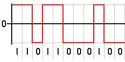
- To send a 1, the sending network card raises the voltage on the wire to +5V for a brief moment.
- To send a 0, it drops the voltage to -5V.
The receiving machine simply watches the voltage and reads the sequence.
This method is called NRZ encoding — Non-Return to Zero. It’s intuitive, efficient, and… deeply flawed.
Step 2 : The Hidden Problem With Simple Voltage Encoding
On paper, NRZ looks perfect. In practice, it hides a subtle but devastating problem: clock synchronization.
Every machine has its own internal clock a crystal that oscillates at a fixed frequency, ticking off time so the machine knows when to “read” the next bit. The sender and receiver each have their own clock, and those clocks are never perfectly synchronized. They’re close, but not identical.
For short transmissions, this doesn’t matter. But imagine the sender transmits a long string of identical bits say, ten consecutive 1s. The voltage stays at +5V the entire time, never changing. Now the receiver has no signal to “latch onto” to resynchronize its clock. And a tiny drift in clock speed accumulates over those 10 identical bits. The receiver might read 9 bits instead of 10, or 11 instead of 10.
This error is called a clock slip, and it silently corrupts data.
On varied bit sequences, this isn’t a problem the frequent voltage transitions give the receiver constant reference points to resynchronize. But long monotone sequences are a ticking time bomb.
There’s a second problem: DC balance. If the signal spends significantly more time at +5V than -5V (or vice versa), the average voltage across the cable drifts away from 0. That DC offset degrades the cable’s reliability over time and introduces random errors. Ideally, you want roughly equal numbers of 1s and 0s, keeping the average voltage near 0V.
Two problems. One clean solution? Not quite.
Step 3 : Manchester Encoding: The Obvious Fix That Isn’t Good Enough
The most straightforward solution to both problems is Manchester encoding.
Instead of representing a 1 as a sustained high voltage and a 0 as a sustained low voltage, Manchester encoding says:
- A 1 is a transition from low to high voltage.
- A 0 is a transition from high to low voltage.
Every single bit no matter what forces a voltage transition in the middle of its time slot. This means:
- Long sequences of identical bits still produce regular transitions → no clock slip.
- Transitions are guaranteed to occur at equal rates in both directions → DC balance achieved.
Manchester encoding is still used today, particularly in older Ethernet standards. But it comes with a serious cost: it cuts your effective data rate in half.
Why? Because each bit now requires two voltage levels within its time slot a low phase and a high phase. Where NRZ could transmit one bit per clock cycle, Manchester encoding needs two clock cycles per bit. You’re burning double the bandwidth to transmit the same amount of data.
At gigabit speeds, this is unacceptable. We need something smarter.
Step 4: The Scrambler: Elegant, Efficient, and Underappreciated
The scrambler is the solution that the networking industry settled on and it’s arguably the most clever trick in this entire story.
The core insight is this: instead of physically modifying how bits are transmitted, modify the bits themselves before transmission to ensure they look pseudo-random.
Here’s how it works:
- Before sending data, the transmitter feeds the original bit stream through a Linear Feedback Shift Register (LFSR) a specific mathematical function that XORs bits together in a predefined pattern.
- The output is a scrambled version of the original data that statistically resembles random noise: roughly equal numbers of 0s and 1s, with frequent transitions regardless of what the original data looked like.
- At the receiver, the exact same LFSR is applied in reverse descrambling the data to recover the original bits perfectly.
The result? You get both DC balance and clock synchronization, without wasting any bandwidth. You’re still transmitting one bit per clock cycle, just like NRZ but now those bits behave the way Manchester encoding forced them to behave.
The scrambler doesn’t slow you down. It just makes your data look random. And random data is exactly what well-behaved physical signals look like.
Step 5: 64B/66B Encoding: Knowing Where the Message Starts
Scrambling solves the signal quality problem. But it introduces a new one: if your data is now a continuous stream of pseudo-random bits, how does the receiver know where one message ends and another begins?
This is the framing problem, and it’s solved by 64B/66B encoding.
The name describes exactly what it does: for every 64 bits of actual data, the encoder adds a 2-bit header at the front, producing a 66-bit block. These 2-bit headers serve as markers:
- They tell the receiver where each data block starts.
- Special command blocks are inserted to explicitly signal the beginning and end of a transmission.
- The regular transitions created by these headers also help the receiver continuously resynchronize its clock.
The overhead is minimal: 2 extra bits per 64 data bits means roughly 3% efficiency loss far better than Manchester encoding’s 50% loss.
The combination of scrambling + 64B/66B encoding is the foundation of most modern high-speed Ethernet standards, including 10GbE and 100GbE.
Step 6: PAM4: Doubling Throughput by Using More Voltage Levels
So far, we’ve been working with two voltage levels: high (+5V) for a 1, low (-5V) for a 0. One voltage level encodes one bit. But what if we used more voltage levels?
That’s exactly what PAM4 (Pulse Amplitude Modulation, 4 levels) does.
Instead of two voltage levels, PAM4 uses four:
- Level 0 (e.g., -3V) → represents
00 - Level 1 (e.g., -1V) → represents
01 - Level 2 (e.g., +1V) → represents
10 - Level 3 (e.g., +3V) → represents
11
Each voltage level now encodes 2 bits simultaneously. At the same signaling rate the same number of voltage transitions per second you transmit twice the data. PAM4 effectively doubles throughput without changing the hardware’s physical speed.
But there’s a serious tradeoff: the four voltage levels are much closer together than NRZ’s two levels. That means noise has much less room to cause a misread before it crosses into the wrong level. A small amount of electrical interference that NRZ would ignore without issue can cause a bit error in PAM4.
PAM4 is used in 400GbE and 800GbE data center interconnects precisely because its environment is controlled and short-range. For long-distance transmission, the noise problem becomes more severe — which brings us to the final piece of the puzzle.
Step 7 :FEC and LDPC – Fixing Errors Without Slowing Down
With PAM4 generating more errors than NRZ, we need a way to detect and correct bit errors automatically — ideally without retransmitting data, and without eating too much of our hard-won bandwidth.
This is the domain of Forward Error Correction (FEC), and the most powerful algorithm used in modern networking is LDPC Low-Density Parity-Check codes.
Understanding Parity: The Sudoku Analogy
To understand LDPC, think about how you’d solve a corrupted Sudoku puzzle.
In a valid Sudoku, every row, column, and 3×3 box must sum to 45. If one number is wrong, several rows, columns, and boxes will produce incorrect sums. The corrupted number is the one that appears in every failing check you can identify and fix it purely by logic, without anyone telling you the answer.
LDPC applies this same principle to binary data:
- The data stream is divided into overlapping chunks each bit belongs to multiple groups.
- For each group, a parity bit is calculated: if the number of 1s in the group is even, the parity bit is 0; if odd, it’s 1.
- These parity bits are added to the transmitted data.
- At the receiver, all the parity calculations are rechecked. If one bit was flipped by noise, several parity checks will fail — but only the corrupted bit will appear in all of them.
- Flip that bit back, and all the parity checks pass again.
Why LDPC Is Special
The key engineering challenge in FEC is efficiency: naively sending every piece of data three times would guarantee correctness but cut your throughput by 67%. That’s obviously not acceptable.
LDPC is remarkable because it provides near-Shannon-limit error correction meaning it corrects errors almost as efficiently as theoretically possible while adding only a modest overhead (typically 7-25% extra bits). Modern 400GbE Ethernet uses LDPC to make PAM4 commercially viable.
It’s not magic. It’s just very good math.
Beyond Copper: Fiber Optics and Radio Waves
Everything above applies to copper cables. But the same fundamental problem — transmit bits reliably across a physical medium — has been solved for other mediums as well.
Fiber Optic Cables
Instead of modulating voltage, fiber optic cables modulate light intensity inside a glass or plastic fiber. A pulse of light represents a 1; no pulse represents a 0 (or, for more sophisticated systems, different intensities represent multiple bits — the optical equivalent of PAM4).
The advantage is extraordinary: light in glass loses very little energy over distance. A fiber optic signal can travel hundreds of kilometers before needing amplification, compared to a few hundred meters for copper. This is why the backbone of the internet — including the submarine cables on the ocean floor that connect continents — is built from fiber optics.
Radio Waves (Wi-Fi and Cellular)
Radio transmission modulates electromagnetic waves rather than voltage or light. The transmitter varies the wave’s frequency, amplitude, or phase — or combinations of all three simultaneously — to encode bits. Wi-Fi’s 802.11ax (Wi-Fi 6) standard, for example, uses 1024-QAM modulation, which encodes 10 bits per symbol by combining amplitude and phase variations.
Radio introduces additional complexity: interference from other transmitters, multipath reflections off walls and objects, and the shared nature of the radio spectrum. These challenges require additional engineering layers — but the core problem being solved is identical.
Putting It All Together
Let’s trace a single click — your mouse button hits a URL — back to its physical foundation:
- Your network card’s software has a sequence of bits it wants to send.
- Those bits pass through a scrambler to ensure pseudo-random distribution.
- The scrambled stream is framed with 64B/66B headers so the receiver knows where blocks start and end.
- FEC (LDPC) parity bits are calculated and appended.
- The complete bit stream is encoded as PAM4 voltage levels and driven onto the copper cable (or as light pulses in fiber, or as radio signals in Wi-Fi).
- At the receiver, the voltage levels are read, LDPC corrects any errors introduced by noise, the 64B/66B framing is stripped, and the stream is descrambled to recover the original bits.
This entire process happens in nanoseconds, billions of times per second, for every byte of data you send or receive.
Key Takeaways
- NRZ encoding is simple but causes clock slips on long runs of identical bits.
- Manchester encoding solves clock slips and DC balance but halves your data rate.
- Scrambling with LFSR solves both problems without any bandwidth penalty — the elegant modern solution.
- 64B/66B encoding adds minimal overhead to frame data streams and ensures synchronization.
- PAM4 modulation doubles throughput by encoding 2 bits per voltage symbol, at the cost of noise sensitivity.
- FEC/LDPC corrects the errors that PAM4's noise sensitivity introduces, using parity mathematics similar to Sudoku logic.
- Fiber optics and radio waves solve the same fundamental problem using different physical media.
Frequently Asked Questions
What is the difference between NRZ and Manchester encoding?
NRZ (Non-Return to Zero) uses a constant voltage level for each bit — high for 1, low for 0. Manchester encoding forces a voltage transition within every bit period: low-to-high for a 1, high-to-low for a 0. Manchester encoding guarantees clock synchronization and DC balance but requires twice the signaling rate for the same data throughput.
What is a clock slip in networking?
A clock slip occurs when the receiver's internal clock drifts slightly out of synchronization with the sender's clock. On long runs of identical bits — where no voltage transitions occur to allow resynchronization — the accumulated drift can cause the receiver to count one too many or one too few bits.
What is a scrambler in networking, and why is it used?
A scrambler transforms a data stream using a Linear Feedback Shift Register (LFSR) to produce a pseudo-random output. This ensures frequent bit transitions and roughly equal numbers of 0s and 1s regardless of the actual data content, solving both clock synchronization and DC balance problems without reducing data throughput.
How does PAM4 differ from NRZ?
NRZ uses two voltage levels to encode one bit per symbol. PAM4 uses four voltage levels to encode two bits per symbol — effectively doubling data throughput at the same signaling rate. The tradeoff is that PAM4 is more sensitive to electrical noise, requiring Forward Error Correction to maintain acceptable bit error rates.
How does LDPC error correction work?
LDPC (Low-Density Parity-Check) divides the data into overlapping groups and calculates a parity bit for each group. When a bit is corrupted in transmission, multiple parity checks fail. The corrupted bit is the one common to all failing checks — analogous to finding an incorrect number in a Sudoku grid. This allows single-bit (and sometimes multi-bit) errors to be corrected without retransmission.
Why are submarine cables made of fiber optics and not copper?
Fiber optic cables transmit light rather than electrical signals. Light in glass loses very little energy over distance, allowing signals to travel hundreds of kilometers before requiring amplification. Copper cables suffer significantly more signal attenuation over distance and are impractical for transoceanic runs. Fiber's long-distance capability makes it the only viable choice for submarine internet infrastructure.